
A Practical Guide to Sigma-1 Receptor Positron Emission Tomography/Magnetic Resonance Imaging: A New Clinical Molecular Imaging Method to Identify Peripheral Pain Generators in Patients with Chronic Pain
By Bin Shen, Daehyun Yoon, Jessa Castillo, and Sandip Biswal
Excerpt from the article published in Semin Musculoskelet Radiol, November 2023; 27(06): 601-617 DOI: 10.1055/s-0043-1775744
Editor’s Highlights
- Sigma-1 receptor (S1R) is a molecular chaperone upregulated under painful conditions to assist ion channels, such as IP3 (inositol-1,4,5-triphospate) and NMDA (N-methyl-D-aspartate) receptors, for pro-nociceptive processes
- S1R PET/MRI helped patients find pain relief after having failed standard management approaches.
Abstract
Accurately identifying the peripheral pain generator in patients with chronic pain remains a major challenge for modern medicine. Millions of patients around the world suffer endlessly from difficult-to-manage debilitating pain because of very limited diagnostic tests and a paucity of pain therapies. To help these patients, we have developed a novel clinical molecular imaging approach, and, in its early stages, it has been shown to accurately identify the exact site of pain generation using an imaging biomarker for the sigma-1 receptor and positron emission tomography/magnetic resonance imaging. We hope the description of the work in this article can help others begin their own pain imaging programs at their respective institutions.
Introduction
Our ability to manage patients with chronic pain remains woefully inadequate. Patients suffering from chronic pain are faced with limited resources and inadequate care, and as a result, they make up the number-one disease group in the world, totaling more than heart disease, diabetes, and cancer combined. Those suffering from low back pain (LBP), headache, fibromyalgia, arthritis, and many other pain syndromes make up this ever-growing population. A big part of our failure to care for chronic pain patients is because our current imaging methods for correctly identifying pain generators remain substantially imprecise. Our ability to accurately identify the cause of a person’s pain, discomfort, inflammation, or other related musculoskeletal symptom(s) using current clinical imaging approaches, such as magnetic resonance imaging (MRI), computed tomography (CT), digital radiography (X-ray), and ultrasonography, is quite limited, lacks sensitivity/specificity, and can even misguide treatment because correlation between the report of pain severity and the presence of underlying pathology is poor.[1] The lack of a reliable diagnostic tool leads to significant misdiagnosis, mismanagement, incorrect use of opioids, unhelpful surgeries, and, ultimately, therapeutic letdowns. A much more accurate and objective imaging method is desperately needed to help those suffering from chronic pain.
To this end, new clinical imaging methods that pinpoint the site of pain generation using imaging probes have emerged, more specifically, positron emission tomography (PET) tracers that specifically target surrogate molecular or cellular markers that are augmented at sites of increased nociceptive activity or inflammation. Using positron emission tomography/magnetic resonance imaging (PET/MRI) and a specific PET radiotracer, [18F]FTC-146, that targets the sigma-1 receptor (S1R), a more sensitive and specific approach has arisen that highlights painful, inflamed pro-nociceptive tissues. S1R is a molecular chaperone that modulates ion channels in the pain pathway that can serve as a biomarker of nociceptive activities. The upregulation of S1R in pain states has been shown to intensify nociceptive processes while its antagonism leads to relief of pain.[2] [3] [4] [5] [6] We have developed a novel radioligand, [18F]FTC-146, for highly specific in vivo PET/MRI detection of S1R upregulation in inflamed, painful tissues[7] [8] [9] and demonstrated its ability to help identify causative pathologies in multiple chronic pain conditions.[10] [11]
More specifically, S1R is a molecular chaperone upregulated under painful conditions to assist ion channels, such as IP3 (inositol-1,4,5-triphospate) and NMDA (N-methyl-D-aspartate) receptors, for pro-nociceptive processes.[6] S1R agonists were shown to inhibit opioid analgesia while antagonists enhance analgesic effects, presumably by modulating G-protein–coupled receptors.[12]
The importance of S1R in pain physiology is further supported by the following key discoveries in both preclinical and clinical trials: (1) Elevated S1R expression in skin and nerve tissues in response to inflammation, ischemic pain, and spared nerve injury[9] [13] [14]; (2) decreased activity of pain-signaling ion channels and attenuated behavioral pain responses with S1R antagonism[14] [15] [16] [17] [18] [19] [20] [21] [22]; and (3) heightened resistance to painful stimuli in S1R knockout mice. S1R is widely distributed throughout the whole body[7] [23] and upregulated focally with localized nociceptive activities. Taken together, these data strongly support the need to quantify S1R expression directly through immunohistochemistry (when possible) and indirectly through PET in an effort to evaluate the correlation between pain and S1R expression in the search for peripheral pain generators at the source of a person’s pain.
The overall goal of this approach is to implement S1R PET/MRI imaging to better inform the location of the pain generator(s) and help demonstrate pathology that facilitates more effective medical, minimally invasive, and/or surgical decisions. Early results have indicated this approach has succeeded in correctly identifying the pain generator in a subset of patients, which, in turn, supported the administration of a management plan that resulted in the patient achieving significant pain relief.
This article provides a practical guide on how to design a clinical trial to pinpoint the site of pain imaging using a highly specific radioligand targeted toward “hyper-nociceptive” or inflamed tissues and PET. Although several potential tracers can be used for this purpose and have been described in other articles in this issue of Seminars, we focus on the S1R radioligand as an example. We begin with a few case studies in which S1R PET/MRI helped patients find pain relief after having failed standard management approaches. These studies are followed by how patients with chronic pain should be selected, important considerations when selecting a pain subtype and referring physicians, imaging techniques, image analysis, and a section regarding the clinical-grade production of the radioligand [18F]FTC-146.
Case Examples
Bilateral Lower Extremity Pain
The first example is a case of a young adult highly talented male football (soccer) player on the training squad for one of the professional football teams in Europe who had severe bilateral lower leg pain. He also experienced bilateral thigh and hip pain, although to a lesser extent than the lower leg pain. The pain was so excruciating, it prevented his participation in practices for the team, and he had to stop playing due to the extreme pain. He eventually progressed in his pain and had significant difficulty in ambulating and was nearly wheelchair bound. All prior work-ups had been negative including bilateral lower extremity MRIs. The patient was diagnosed with compartment syndrome and underwent bilateral fasciotomies of the lower leg that ultimately proved unsuccessful in alleviating pain. Failing all standard-of-care procedures, the patient presented to the S1R PET/MRI study to determine the site of pain generation.
The scan revealed increased S1R radiotracer uptake in the bilateral anterior lower leg muscle compartments, specifically in the extensor digitorum longus and extensor hallucis longus muscles (maximum standardized uptake value [SUVmax] = 5.4 (right foreleg) and 3.6 (left foreleg) ([Fig. 1]). Abnormal uptake of radiotracer was also observed in the popliteus muscles, the left greater than the right. The findings in these extensor muscles and popliteus muscles appear to correlate well with the locations of the individual’s symptoms. Of note, there was no MR signal abnormality in these muscles; the muscles were all normal in appearance, volume, and signal intensity ([Fig. 2]). Additionally, a review of the previous MR scans of the legs from an outside imaging facility also showed that these muscles were normal by MR criteria. Abnormal S1R radiotracer uptake was also visualized in the plantar aspect of the left foot, bilateral quadriceps muscles, and bilateral gluteus medius muscles.
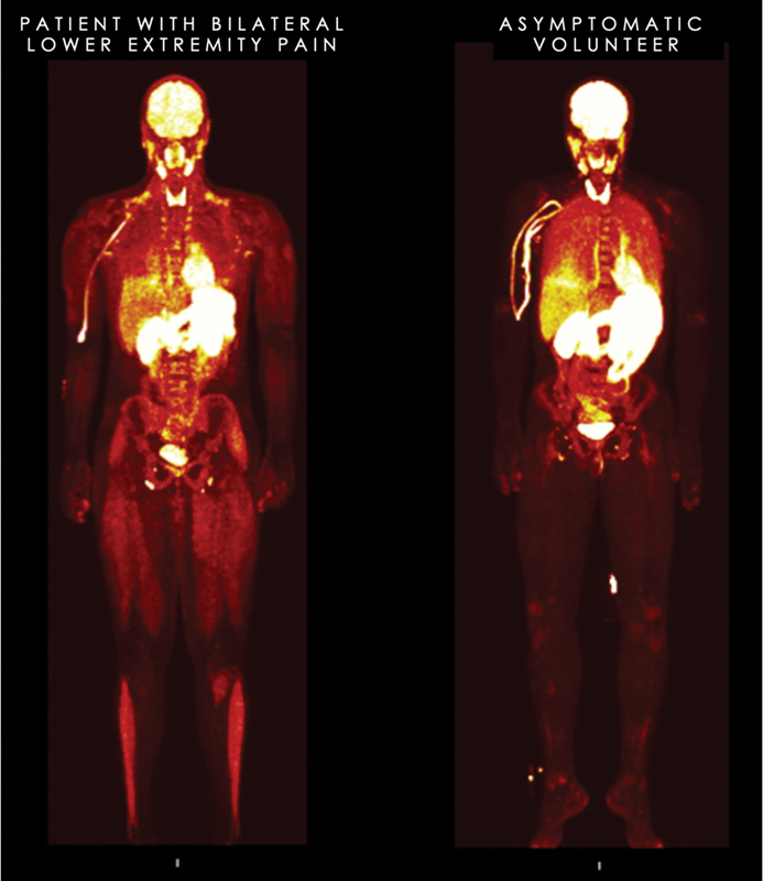
Whole-body sigma-1 receptor (S1R) positron emission tomography image (three-dimensional maximum intensity projection of young adult male patient with bilateral lower leg pain (image on left) compared with asymptomatic volunteer (image on right). Patient shows abnormally increased uptake in the muscles of the lower leg in the region of maximum symptoms and also, to a lesser extent, his quadriceps where there was also thigh discomfort, although substantially less than the lower legs. Normal physiologic uptake of the S1R tracer can be observed in the brain, thyroid, kidneys, blader, proximal gastrointestinal tract, heart, and, to a lesser extent, in the lung and liver in both the patient and volunteer.
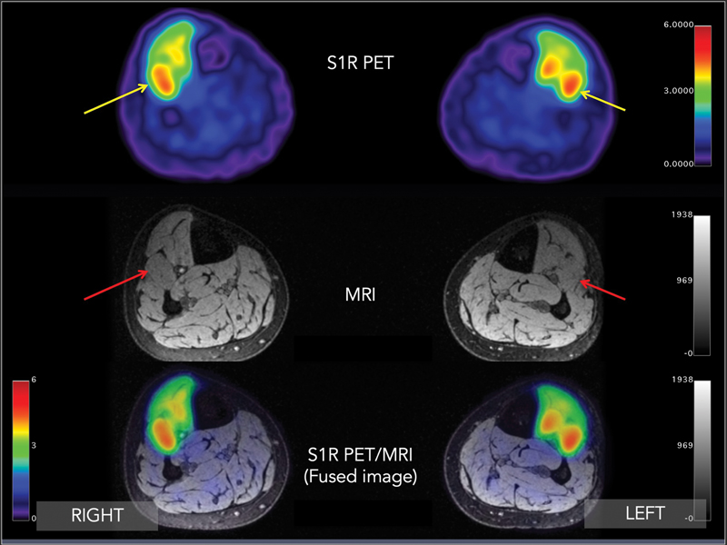
Transverse (axial) sigma-1 receptor positron emission tomography/magnetic resonance image (PET/MRI) through both lower legs at approximately the midcalf level. Increased uptake in bilateral anterior compartments of both lower leg muscles. Maximum standardized uptake value (SUVmax) = 3.2 (right) and 3.5 (left) (yellow arrows), especially in the extensor digitorum longus muscle (red arrow). Of note, background SUVmax is typically in the range of 0.2 to 0.5.
Based on the patient’s clinical presentation and that he had failed two previous fasciotomies, a decision was made to infiltrate the anterior compartment and proximal aspects of the proximal posterior compartment with botulinum toxin injections in both legs. The patient had significant improvement in symptoms, and he returned to play.
Right Neck Pain
A young adult woman sustained an injury during rock climbing several years before her presentation to our clinic. She described a sharp and intense chronic pain in the right neck, shoulder, and upper back. Her symptoms were exacerbated by stress or carrying things or lifting and range from 6 to 10 of 10 on the Numeric Rating Scale (NRS). Her pain would flare toward 10/10 when she would experience periods of stress in her occupation. Previous diagnostic work-up earlier included a cervical spine MRI that showed no significant spinal stenosis, disk herniation, facet arthropathy, or neural impingement. Other diagnostic studies revealed she did not have provocative spondylolisthesis in the cervical spine, and she did not have evidence for an inflammatory arthropathy. Diagnostic injections included a cervical epidural that provided temporary relief. She also underwent standard-of-care trigger point injections combined with physical therapy, as well as a right C3–C4 facet joint block, neither of which provided any relief. She eventually presented for an S1R PET/MRI scan to better localize her source of pain.
S1R PET/MR imaging revealed increased S1R radiotracer uptake in the right greater left longissimus cervicis, multifidus, and rotatores cervicis muscles from approximately the C3 level to just beyond the C7 level ([Figs. 3] and [4]). Correspondingly, MR images show no abnormal signal, muscle edema, atrophy, or fatty replacement. The abnormal PET findings in this case suggested that the primary pain generator was the muscle themselves and were likely inflamed and acted as trigger points for the patient’s symptoms, perhaps the result of myofascial pain syndrome.
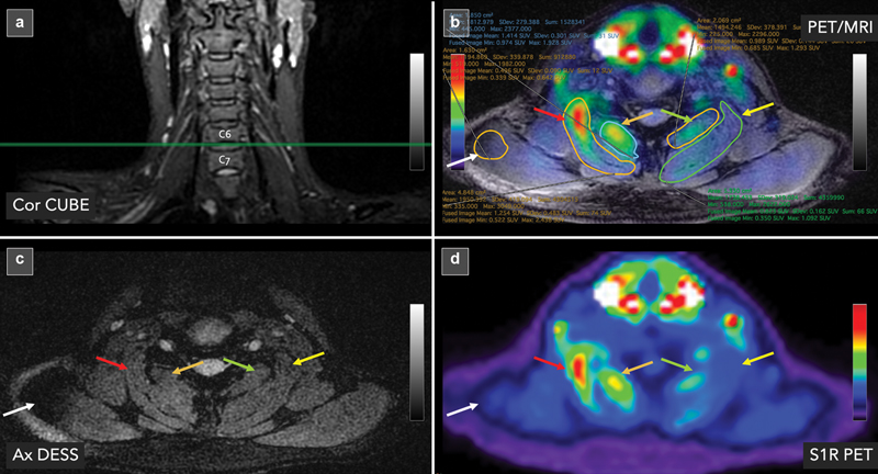
Sigma-1 receptor (S1R) positron emission tomography/magnetic resonance (PET/MRI) images of a young adult woman with years of debilitating right neck discomfort. (a) Coronal CUBE MR image through the cervical spine shows the location of the axial images from (b), (c), and (d) located at the C6–C7 level (horizontal green reference line). (b) Axial fused S1R PET/MR image at C6–C7 with regions of interests drawn around the muscles that have demonstrated abnormalities on PET/MRI. (c) Of note, the MRI shows no tissue injury, neural impingement, or abnormal signal in the paraspinal tissues. MRI is essentially normal. (d) S1R PET shows increased uptake in the right longissimus cervicis muscle (SUVmax = 2.44; red arrow) and, to a lesser extent, the right multifidus/rotatores cervicis muscles (SUVmax = 1.93; orange arrow). These SUVs are higher than the contralateral left longissimus cervicis muscle (SUVmax = 1.09; yellow arrow) and the left multifidus/rotatores cervicis (SUVmax = 1.29; green arrow). For reference, background muscle (trapezius) at this level (SUVmax = 0.64; white arrow) has been sampled.
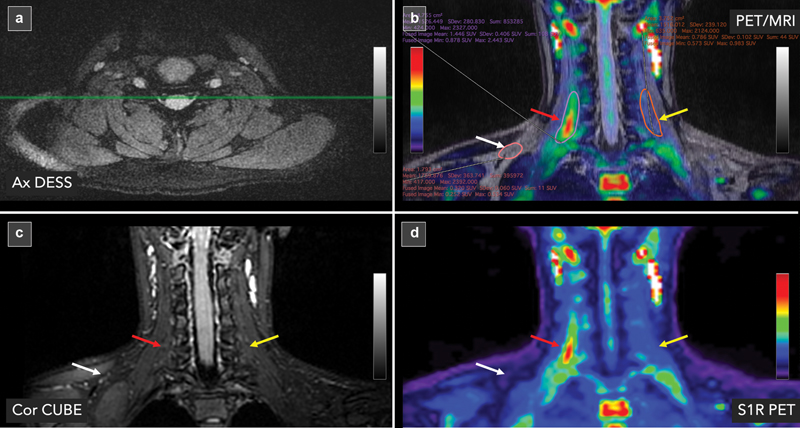
Sigma-1 receptor (S1R) positron emission tomography/magnetic resonance (PET/MRI) images of a young adult woman with years of debilitating right neck discomfort. The images depicted in this figure are from the same patient as [Fig. 3] but depicted in the coronal plane. (a) Axial double echo in a steady state (DESS) MR image through the cervical spine shows the location of the coronal images from (b), (c), and (d) in the cervical spine (horizontal green reference line). (b) Coronal fused S1R PET/MR image through the cervical spine is shown with regions of interests drawn around the muscles that have demonstrated abnormalities on PET/MRI. (c) Of note, the MRI shows no tissue injury, neural impingement, or abnormal signal in the paraspinal tissues. MRI is essentially normal. (d) S1R PET shows increased uptake in the right longissimus cervicis muscle (maximum standardized uptake value [SUVmax] = 2.44; red arrow). These SUVs are higher than the contralateral left longissimus cervicis muscle (SUVmax = 1.09; yellow arrow) and the left multifidus/rotatores cervicis (SUVmax = 0.38; green arrow). For reference, background muscle (trapezius) at this level is (SUVmax = 0.53; white arrow) has been sampled.
The patient eventually underwent CT-guided injection with a medication containing anesthetic and dexamethasone into both the right longissimus cervicis and multifidus muscles. The injections were guided into the precise location of greatest tracer accumulation, which was cross-referenced with the location determined on the simultaneous acquired MRI at the time of PET acquisition ([Fig. 5]). The patient subsequently felt significant relief from this procedure in the neck. Her pain scores maintained a lower level of pain at 2 of 10 and did not change with added stress. The patient did describe other sites becoming more painful (that were untreated), likely to do with the unmasking of other painful sites in her body. The patient did state that she never “had felt this good after an injection” and she had never been able to say she “feels zero pain after an injection.” In the period following the injection, the patient experienced an extended period of diminished pain for a few weeks.
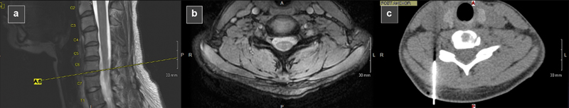
Images of the cervical spine showing how anatomical magnetic resonance (MR) images were used to help plan the computed tomography (CT)-guided injection of the right longissimus cervicis muscle with anesthetic and steroid. (a) Sagittal MR image shows location of axial MR image (yellow dashed line). (b) Axial image through the cervical spine that represents the location of the positron emission tomography abnormality seen in [Fig. 3]. (c) CT-guided injection of the right longissimus cervicis muscle at the same location as shown in the MR slice. CT image has been flipped to match the corresponding MR image for illustrative purposes only.
Discriminating between Painful versus Nonpainful Peripheral Nerve Sheath Tumors
Peripheral nerve sheath tumors (PNSTs) are relatively common, occurring in ∼ 40 of 100,000 individuals.[24] [25] [26] [27] They occur in benign (BPNST) and malignant (MPNST) forms and occur both sporadically (nonsyndromic) and in association with neurogenetic conditions (syndromic), including neurofibromatosis type 1 (NF1), NF2, and schwannomatosis. The management of individuals with PNSTs is challenging, and pain is a common and unfortunate experience for those with PNSTs. The clinical manifestation of these tumors is quite varied, ranging from an incidental finding and an asymptomatic palpable or visible mass, to those who experience weakness, tingling, and/or severe pain. Pain associated with these tumors, particularly when multiple tumors are present such as those with neurofibromatosis and schwannomatosis, can be significant and lead to a major disability and poor quality of life.[28] [29] [30] [31] Nearly a fifth of those with PNSTs are currently prescribed an opioid pain medication.[32]
Surgical resection to remove painful PNSTs are an option, and favorable outcomes can be achieved, with nearly 85% of patients undergoing resection showing improvement in pain postoperatively.[33] However, the specific pain-generating tumor, especially in individuals with multiple tumors, can be difficult to identify precisely, given the variable contribution to the pain between tumors within an individual. Led by neurosurgeon Thomas J. Wilson at Stanford University, S1R PET MRI is being used to discriminate between painful versus nonpainful PNSTs. Preliminary results have indicated that painful tumors take up more S1R radiotracer in a more eccentric pattern ([Fig. 6]). By comparison, nonpainful PNSTs take up the radiotracer in relatively low amounts ([Fig. 7]).
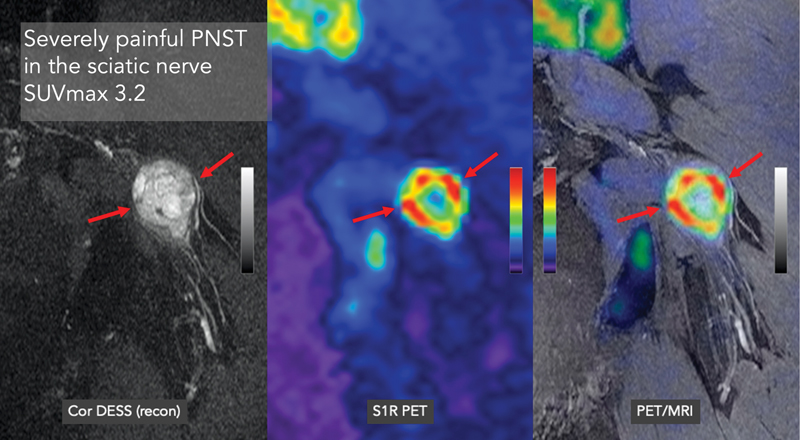
Patient was found have a severely painful (numerical rating scale: 8/10) peripheral nerve sheath tumor (PNST) in the left sciatic nerve as seen in the coronal magnetic resonance imaging (MRI) (left image, red arrows). MRI showed a moderate size relatively heterogeneous mass of increased signal intensity on double echo in steady state (DESS) imaging located in the sciatic nerve, displacing some of the components of the sciatic nerve to course around the mass. Sigma-1 receptor positron emission tomography (PET) imaging revealed patchy high uptake of the radiotracer throughout the mass with an SUVmax of 3.2 (middle and right image; red arrows).
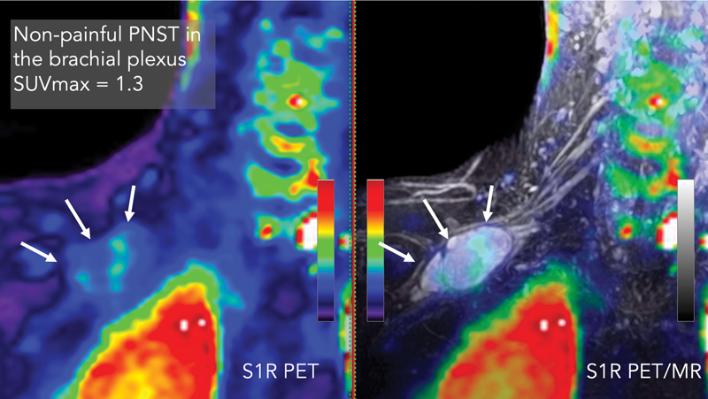
Patient was found have an incidental, non-painful (numerical rating scale: 0/10) peripheral nerve sheath tumor (PNST) in the right brachial plexus as seen in the coronal magnetic resonance imaging (MRI) (right image, white arrows). MRI showed a moderate size relatively homogeneous mass of increased signal intensity on double echo in a steady state (DESS) imaging located in the brachial plexus, displacing some of the components of the brachial plexus to course around the mass. Sigma-1 receptor (S1R) positron emission tomography (PET) imaging revealed relatively low uptake of the radiotracer throughout the mass with an SUVmax of 1.3 (left image, white arrows).
Clinical Methods to Image Chronic Pain Patients with S1R PET/MRI
Selection of Patients
The number of individuals suffering from pain now makes up the largest medical population in the world. Pain arises from headache, LBP, joint pain, postsurgical pain, fibromyalgia, complex regional pain syndrome (CRPS), and more. The list is long. This section provides guidance on which pain populations to recruit for the study.
When setting up a clinical trial, the Clinical Trials Office (or similar regulatory body within the health-care entity) will require the trial be posted to clinicaltrials.gov site and/or websites of the health-care entity. Given the public nature of such announcements and the large number of potential chronic pain patients, it becomes imperative to focus on a single or small number of pain syndromes. Rather than take all comers, it is perhaps best to focus on one to three specific pain syndromes or pain types. Recruiting everyone, although intriguing, will make for a databank that is quite heterogeneous in composition, making it challenging to draw any conclusions and maintain any consistency in management plans. Restricting the inclusion criteria to just a single or small number of pain types will facilitate a focused approach and more meaningful learning curve as the nuanced (or overt) differences between patients within that specific pain syndrome are appreciated. Eventually as experience is gained with a specific patient group, clinicians will feel more adept at including other pain subtypes in the future.
Additionally, selecting a specific pain syndrome that can potentially be adequately treated is preferable than selecting a pain syndrome where treatment options are limited. As a suggestion, we believe pain syndromes such as LBP, sciatica, postsurgical pain, myofascial pain syndrome, and large joint pain (shoulder, hip, and knee) would be a reasonable place to start because these pain types have a variety of medical, minimally invasive, and surgical options available. Having several therapeutic options available will provide the highest possibility for a favorable outcome because the imaging results may reveal findings that respond favorably to specific applications.
Conversely, selecting a pain syndrome that has limited management options means that there will likely be little change in outcomes for the patient even if the findings on the PET/MR imaging are positive. Pain syndromes, such as diabetic neuropathy and CRPS, have limited therapeutic options and are generally managed with systemic medications. Because the management options are narrow in these cases, the utility of PET/MRI, although of academic interest, will be limited, despite a strong likelihood the imaging will find positive imaging findings. Yoon et al in 2022 showed that individuals suffering from lower extremity CRPS demonstrate radiotracer uptake patterns that quite varied between individuals despite having the same diagnosis. That is, one patient may show skin and muscle uptake in the lower extremity while another shows neurovascular uptake despite both meeting strict criteria for the diagnosis of lower extremity CRPS.[34] Of note, this comment is not meant to avoid the study of such challenging patients but just to suggest that in the evaluation of a new radiotracer, it is better to select a patient population with more manageable pain conditions. Ultimately, this imaging approach will be helpful to these patients with more poorly understood conditions in that this approach can aid in the eventual development of novel medications or alternative personalized therapeutic approaches by pharmaceutical and biotechnology companies in the not-too-distant future.
Referring Physician
Aligning with a referring physician who has also experienced challenges of pain diagnosis and is interested in this approach will not only help provide a regular, robust source of research subjects for the trial, but also the physician will have a vested interested in making management decisions based on the findings. Partnership with a committed collaborator is critically important in not only developing credibility of the approach but will also have important ramifications in building a community of interested caregivers and patient referrals.
An example of a pain subtype that appears to lend itself to finding collaborators/referring physicians are surgeons who deal with those individuals who have failed surgical intervention, (e.g., persistent postsurgical pain, post-arthroscopy pain, failed back surgery syndrome). Contacting colleagues in neurosurgery, orthopaedic surgery, pain (anesthesia), pediatric pain, neurology, or physical medicine and rehabilitation will likely yield collaborators who will be willing to refer subjects for this study because they most certainly have a subset of diagnostically challenging patients.
Inclusion/Exclusion Criteria: Low Back Pain as a Case Example
Each pain type has specific inclusion and exclusion criteria. In general, test subjects should have a minimum NRs or VAS score ≥ 4 to qualify for the study, not be claustrophobic undergoing an MRI, are free of devices that are incompatible with MRI, and are not pregnant.
As an example, we provide selection criteria for those individuals with LBP, which is fraught with misdiagnosis because the cause of pain in these patients is unknown in 80 to 90% of the cases.[35] [36] [37] [38] Furthermore, imaging methods (radiography, CT, MRI) that have been routinely used for the past few decades for diagnosis for pain generation in this group, but identified structural or signal abnormalities using this approach, have not been a reliable marker for pain. For example, a literature review study showed disk degeneration and signal loss present in ∼ 90% of asymptomatic individuals ≥ 60 years of age.[39] High-intensity zone lesions and spondylitic defects did not show significant association with severity of LBP.[40] This diagnostic inaccuracy has resulted in inadequate pain management, and LBP ranks among top conditions leading the prescribed opioid use in primary care[41] [42] [43] despite the elevated risk of addiction, complications, and poor surgical outcome.[44] [45] [46] [47] Clearly, better diagnostic methods are needed to develop effective therapies for LBP and to eliminate the need for opioids.
| Inclusion |
| • Pain is located in the lower back, between bottom of ribs and buttock creases. Pain below buttock crease can be included. |
| • Age ≥ 21 and ≤ 70 y. |
| • Duration: Back pain problem that developed less than a month ago and has persisted at least 3 mo. |
| • Baseline pain: NRS ≥ 4; VAS ≥ 40. |
| Exclusion |
| • Evidence of fracture, infection, or malignancy. |
| • Rheumatologic conditions excluded are ankylosing spondylitis or related conditions. |
| • Medicolegal issues, not understanding language, previous or scheduled surgery, psychiatric disorders including evidence of depression and other major mental health issues before LBP. |
| • Inability to understand and communicate with the investigators to complete the study-related questionnaires. |
| • Patient currently enrolled in another study. |
| • Any comorbidity that results in severe systemic disease limiting function (as defined by the American Society of Anesthesiology physical status classification), such as the presence of current or past pulmonary, hepatic, renal disease, arthritis, hematopoietic, and neurologic diseases not related to LBP. |
| • Pregnancy test for women is positive. |
| • Non-English language. |
Abbreviations: LBP, low back pain; NRS, Numerical Rating Scale; VAS, Visual Analog Scale.
Instructions to Patients
Research subjects, which will include patients suffering from a specific type of pain control, and controls, asymptomatic volunteers, will need to complete and sign an informed consent form before the scanning session. Although no side effects are expected from the intravenous administration of trace amounts of the radioligand, patients are warned of possible side effects from the administration of the radiotracer and of the relatively low radiation exposure from the radiotracer itself.
Depending on the needs of the study, a variety of pain questionnaires need to be completed. Specific pain syndromes have specific pain questionnaires tailored to the specific patient experience, but a collection of forms may include the VAS, SF-36 Health Survey, Oswestry Disability Index, and Health Utilization Record, for example. The specific selection of forms should be reviewed with the referring physician to ensure consensus on the most important metrics to capture. Electronic versions of the forms can be e-mailed, or, alternatively, paper versions can be mailed to the subject’s home. These forms should be completed just before or the evening before the scanning session so symptoms are as closely temporally aligned as possible to the day of the image acquisition. The completed forms will eventually be used to correlate the pain-relevant metrics derived from these forms with the imaging results.
Subjects should be instructed not to eat anything at least 2 hours prior to the scan. They are permitted to drink water. The fasting period may vary depending on the radiotracer studied. For example, if the subject was to receive [18F]fluorodeoxyglucose, the fasting period should be a period of 4 hours just before the scan.
Research subjects, especially those from chronic pain, will likely be taking medications for treatment of their pain. If subjects can tolerate decreasing or eliminating pain medications 1 to 3 days prior to the scan, this appears to help enhance PET/MR signal in the areas of increased inflammation/nociceptive activity. If the patient cannot tolerate lowering the dose or eliminating pain medications temporarily without experiencing a major pain exacerbation, they should refrain from doing so. Specific medications that should not be stopped are gabapentin and any medications that the subjects believe will have a clinically significant, debilitating exacerbation of their symptoms if they were to discontinue the medication. That said, subjects should ideally present to the scan with an NRS/VAS score ≥ 4 whether or not they temporarily stopped or decreased their pain medications.
A clinical research coordinator assigned to the study should contact the patient and schedule a scan for a given subject on a day the radiochemistry facility is able to produce a [18F]FTC-146 dose and when the patient can take time off from work. Typically, the schedule is set ∼ 3 to 4 weeks ahead of time. A map of the scanner location and directions for parking should be provided to the patients. The patient should also be given the name and phone number of the clinical research coordinator and PET/MRI (or PET/CT) technologist. This information should be offered to the patient before the scan date in the event the patient needs to reach one of these key individuals involved in the study.
On the day of the scan, the PET/MR technologist or clinical research coordinator should receive the patient in the lobby of the study site and guide them to the scanner. Depending on the imaging facility’s policy, either a negative pregnancy test administered before the scan (only for a female subject who is of childbearing age) or verbal confirmation denying an active pregnancy will be required. A positive pregnancy test or admission of an active pregnancy on the day of the scan will result in cancellation of the study.
Study subjects will be instructed to change into the appropriate attire provided that includes scrubs and socks. The technologist will check and record vitals of the study subject, including temperature, heart rate, and blood pressure. The technologist will also place an intravenous catheter into the antecubital vein for administration of the radiotracer. If the research subject has unilateral arm pain, the catheter should be placed on the opposite arm.
Study subjects should be warned that there is possibility of the scanner failing (∼ 1 in 30 scans), and the study will have to be canceled or postponed in the event that the scanner fails. Furthermore, the study subjects should be told that they will be at the scanner for a total of ∼ 3 to 4 hours that includes the 1- to 1.5-hour imaging session itself.
Positron Emission Tomography/Magnetic Resonance Imaging Scanning
Our PET/MRI scan protocol is composed of these sequential steps: (1) Pre-imaging preparation, (2) 30-minute dynamic brain PET/MRI, (3) 10-minute break, (4) 1-hour whole-body PET/MRI, (5) 15-minute extremity PET/MRI if necessary, and (6) post-imaging evaluation. Pre-imaging preparation entails a review of the patient’s history and deciding the location (specific bed positions) of additional higher resolution sequences for the whole-body acquisition, as well as specific bed positions and additional sequences for the optional 15-minute extremity acquisition.
Thirty-minute Dynamic Brain PET/MRI
Note that the radiotracer injection is conducted after the MRI brain angiogram is finished. A head/neck coil, two anterior body array coils, and a spine coil are used for the brain and whole-body MRI scan. A flex coil is used for the MRI scan of extremities if the optional extremity PET/MRI is conducted. Although a variety of PET/MRI systems from different makers is available and can be used to perform pain imaging, some of the parameters given here are specific to our experience with the GE SIGNA PET/MRI (time-of-flight PET/3.0-T magnet). Here is a stepwise method to scan the brain:
- Measure the radioactivity of the delivered tracer and match it to the preordered dose (11 mCi). The whole-body imaging requires a 10 mCi dose for the [18F]FTC-146 radiotracer as of this writing.
- Conduct MRI screening of the subject and confirm the subject has no contraindications for the scan.
- Have the subject change clothes to prepared scrubs that do not contain any metallic material. The subject should not carry any metallic belongings (e.g., rings, necklace, piercings, etc.) until the scan is complete.
- Measure the vital signs of the subject, including blood pressure, heart rate, pulse oxygenation level, and temperature, to confirm the subject is stable to have the PET/MRI scan.
- Place the angiocatheter into an arm of the subject for the radiotracer injection. If one of the patient’s arms is the main target area of imaging, avoid the arm for the injection. Flush the catheter with a syringe filled with saline for testing.
- Admit the subject to the PET/MRI scanner, and place the subject’s head inside the head/neck coil.
- Conduct the MRI angiogram of the brain to capture the carotid arteries below the circle of Willis. The MRI angiogram is a three-dimensional (3D) axial gradient-echo sequence with these parameters: TR/TE: 27/2.7 ms; flip angle: 15 degrees; bandwidth: ± 31.25 kHz; field of view (FOV): 24 × 21 cm; matrix size: 384 × 338; slice thickness: 1.2 mm; number of slices: 64; number of excitations (NEX): 0.85. Parallel imaging acceleration (phase × slice): 2 × 1. A saturation band is placed to cover the brain region above the prescribed FOV.
- Prescribe the PET/MRI scan of the brain, with the PET scan set to begin automatically after the photon count reaches a predetermined threshold; the MRI scan is set to begin with a manual user input. An example of a prescription of the PET imaging parameter is as follows:
- Diameter FOV: 30 cm; matrix size: 192 × 192; slice thickness: 2.7 mm; number of slices: 89. Image reconstruction method: Ordered subset expectation maximization with 28 subsets and 2 iterations, in-plane smoothing kernel: Gaussian filter with 3.5 mm full-width at half-maximum.
- Measure the total radioactivity of the syringe filled with the radiotracer and the tracer volume. Record the time when the measurement was done.
- Inject the radiotracer into the catheter placed at the arm of the subject and record the time of the injection.
- Start the MRI scan. Note that the PET scan is automatically started with the injection when the PET detectors start to receive the radiation from the tracer in the subject. The MRI scan protocol is composed of these MRI sequences: 3D axial spoiled gradient-recalled echo with 2-point Dixon, 2D axial T2-weighted fast spin-echo with triple-echo Dixon, and 3D axial spoiled gradient-recalled echo with inversion recovery magnitude preparation. The pulse sequence parameters of each sequence are as follows:
- 3D axial spoiled gradient-recalled echo with 2-point Dixon (LAVA-FLEX). TR/TE: 27/1.2 ms; flip angle: 15 degrees; bandwidth: ± 142.86 kHz; FOV: 42 × 33.6 cm; matrix size: 356 × 284; slice thickness: 2 mm; number of slices: 120; NEX: 1. Parallel imaging acceleration (phase × slice): 2 × 2.
- 2D axial T2-weighted fast spin-echo with triple-echo Dixon (T2-FLEX). TR/TE:4s/68 ms; refocusing flip angle: 125 degrees; bandwidth: ± 166.67 kHz; FOV: 38 × 30.4 cm; matrix size: 288 × 230; slice thickness: 4 mm; number of slices: 60; echo train length: 16; NEX: 1. Parallel imaging acceleration (phase × slice): 2 × 1.
- 3D axial spoiled gradient-recalled echo with inversion recovery (BRAVO). TR/TE: 9.6/3.8 ms; flip angle: 13 degrees; bandwidth: ± 2 5 kHz; FOV: 24 × 19.2 cm; matrix size: 256 × 204; slice thickness: 1 mm; number of slices: 200; NEX: 1. Parallel imaging acceleration (phase × slice): 2 × 1; inversion time: 400 ms.
- Take the subject out of the scanner suite after the brain PET/MRI scan is finished.
- Remove the intravenous catheter and measure the radioactivity of the catheter and syringe. Record the time of this radioactivity measurement. The pre-injection and post-injection radioactivity measurements and times are used for the PET image reconstruction.
- Have the patient go to the restroom to micturate to remove radiotracer that has collected in the bladder at this point and facilitate the removal of unbound radiotracer in the bloodstream of the subject.
One-hour Whole-Body PET/MRI (Stage I)
As in the previous section, a stepwise set of instructions for whole-body PET/MR imaging is as follows:
- 1. Readmit the subject to the PET/MRI scanner. Place the head/neck coil and anterior body coils on the subject.
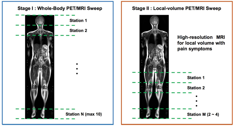
- 2. After running the whole-body localizer, prescribe the whole-body PET/MRI scan of 9 to 10 bed positions to cover from the head to toe as shown in the following example ([Fig. 9]).
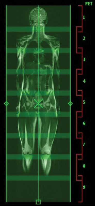
Whole-body prescription.
Stage 1 (whole-body) and Stage II (optional extremity imaging). MRI, magnetic resonance imaging; PET, positron emission tomography.
For each bed position, prescribe the LAVA-FLEX and T2-FLEX MRI sequences used for the dynamic brain PET/MRI scan using the same scan parameters. The overlap between the adjacent bed positions is adjusted (18 to 24 mm or above) to place the target area of interest (if any) in the center of a bed station. Example of PET imaging acquisition parameters for each bed position are as follows:
- Diameter FOV: 60 cm; matrix size: 192 × 192; slice thickness: 2.7 mm; number of slices: 89; Image reconstruction method: Block sequential regularized expectation maximization with regularization parameter β = 250.
- 3. The following two MRI sequences can be added to those bed positions including the region of symptomatic torso areas, including the spine (cervical, thoracic, lumbar) and pelvis.
- 3D axial double echo in steady state (DESS). TR/TE: 16.8/5.96 ms; flip angle: 30 degrees; bandwidth: ± 41.67 kHz; FOV: 25 × 50 cm; matrix size: 300 × 600; slice thickness: 1.5 mm; number of slices: 190; NEX: 1. Parallel imaging acceleration (phase × slice): 2 × 2.
- 3D coronal fast spin-echo with triple-echo Dixon and motion-sensitized driven-equilibrium magnitude preparation (MSDE-CUBE-FLEX). TR/TE: 2.5s/75.5 ms; bandwidth: ± 200 kHz; FOV: 36 × 28.8 cm; matrix size: 256 × 204; slice thickness: 1.4 mm; number of slices: 240; echo train length: 84; NEX: 1. Parallel imaging acceleration (phase × slice): 2 × 2; velocity encoding: 1.7 cm/s (all directions). Outer-volume-suppression was used to saturate the signal outside the prescribed phase FOV.
- 4. Specify the acquisition time of the PET for each bed position with the total scan time of MRI sequences included in the bed position. This is because the total MRI scan time for each bed position is usually longer than the minimal PET scan time (∼ 3 minutes) that produces a reasonable signal-to-noise ratio.
- 5. Start the whole-body PET/MRI scan. Two anterior body coil arrays are typically not long enough to cover the subject’s whole body. Therefore, before entering the bed position that is not covered by these coils, pause the scan and move the coils to cover the rest of the bed positions.
Optional 15-minute Extremity PET/MRI (Stage II)
- If an additional PET/MRI scan of extremities is needed to collect high-resolution MRI images (Stage II; [Fig. 8]), remove the coils used for the whole-body scan. Place the flex coil around the extremity of interest.
- Prescribe and run an additional PET/MRI scan for the target extremity. The PET acquisition parameters can be imported from the whole-body PET acquisition parameters. Adopt MRI sequences customized to the target anatomy. Following is an example of a sagittal DESS scan to cover a whole knee. The total scan time here is limited to < 15 minutes to avoid patient discomfort.
- 3D sagittal double echo in steady state (DESS). TR/TE: 21.4/7.02 ms; flip angle: 30 degrees; bandwidth: ± 41.67 kHz; FOV: 16 × 16 cm; matrix size: 320 × 320; slice thickness: 0.8 mm; number of slices: 210; NEX: 1. Parallel imaging acceleration (phase × slice): 2 × 2.
Post-scan Evaluation
- After all PET/MRI scans are finished, take the subject out of the scanner and measure vital signs again to see if the subject presents any sign of abnormalities.
- Have the subject change clothes and leave the PET/MRI suite. Subjects are encouraged to stay away from small children and sleep in a bed away from others for the next 24 hours to allow complete decay of injected radiotracer material.
Image Analysis
Image Reviewers
Those embarking on pain imaging for the first time will need some combination of both a radiologist to interpret the MRI and a nuclear medicine physician to interpret the PET. Radiologists, especially those with specialty training in musculoskeletal imaging and/or neuroradiology, will be needed to corroborate any underlying morphological or signal abnormalities on MR imaging. Whether a musculoskeletal radiologist or neuroradiologist is used depends on the body part in question. Extremity, trunk, and pelvic pain are best served by a musculoskeletal imaging radiologist, whereas pain syndromes like headache, trigeminal neuralgia, and occipital neuralgia are the domain of the neuroradiologist. Those with spine-related pain can be read by either type of radiologist. All studies will be served well by a nuclear medicine physician to help with PET interpretation and to assist with any PET imaging artifacts.
Initial interpretation of [18F]FTC-146 PET/MRI images should be performed without knowledge of the patient’s history to minimize bias. Using only the imaging findings, image reviewers will mark if the images show painful lesions or not. The marked answer will be compared with the subject’s location of painful symptom(s) to determine whether it is correct or not once the history is eventually revealed.
Digital Imaging and Communication in Medicine (DICOM) images of all of the imaging PET and MRI data are loaded onto a computer containing a DICOM viewer such as Osirix (Pixmeo SARL, Switzerland) or Horos (Horos Project, United States). The latter is free to download on a personal computer. Alternatively, Mirada XD (Mirada Medical) and MIMS Encore (MIMS Software) can be used that can potentially be integrated into a hospital picture archiving and communication (PACS) system. These DICOM viewers are excellent at coregistering PET and MR data, performing custom-drawn region-of-interest (ROI) measurements, adjusting window length and width on both PET and MR data, and measuring SUVs (maximum, mean, and minimum) on PET data.
- Before analyzing the image data, the PET is visualized using the PET or National Institutes of Health color look-up table. The SUV window range is set from 0.0 to 2.0 or 0.0 to 3.0.
- To categorize lesions in the lumbar spine, for example, ROI analysis is performed for [18F]FTC-146 uptake by segmenting areas of the lumbar spine on axial images according to traditional anatomical compartments. Using the coregistered MR imaging, each lumbar spine level (L1–L5) can be segmented into disk, lateral recess, neuroforamen, facet joint, and paraspinal muscle using an ROI tool that can draw custom shapes. Standardized uptake value (SUV) metrics can be derived from the ROI and recorded. To establish baseline measurements of [18F]FTC-146, we calculated the mean and standard deviation of the SUVmax in those same segmented areas on asymptomatic control subjects. For all detected lesions, both spinal and nonspinal, the measured SUV⌝max is compared with the contralateral SUVmax. [Fig. 10] provides a sample ROI analysis of a herniated lumbar disk.
- Attention is also directed at identifying background radiotracer uptake so target-to-background calculations can be made. Background activity can be measured in a variety of locations where activity is consistently low, such as subcutaneous fat, marrow spaces in the lower extremities, and within the cerebrospinal fluid of the spinal canal, to list a few.
- It is highly recommended that consultation with a biostatistician occurs before onset of the study because several study designs and types of measurements/analyses should be considered. Collecting the appropriate data and normalization data should be clarified with an expert to optimize study design. Careful consideration should be directed toward how to correlate pain behavior measurements (e.g., location of pain, intensity of pain, quality of pain, duration, management of pain, etc.) with imaging findings. Also, longitudinal study designs, where patients are scanned before and after treatment, should also be considered.
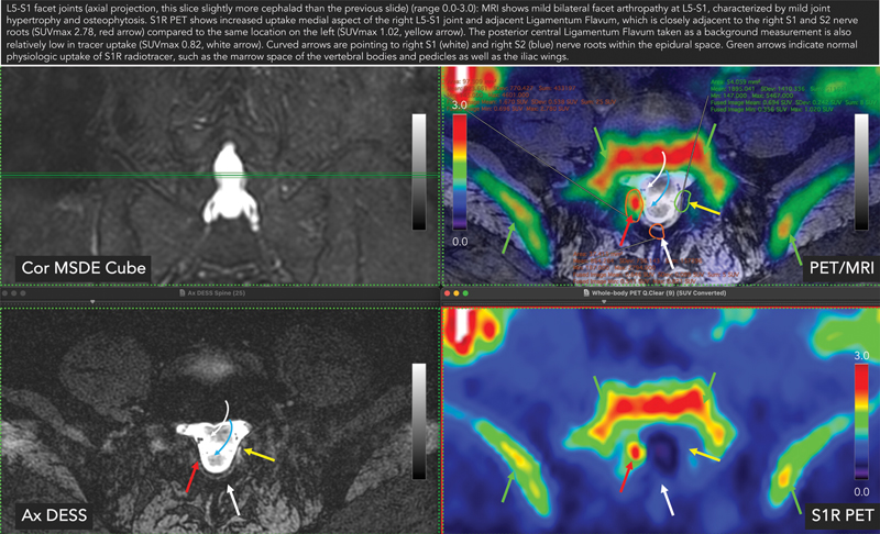
Sample region-of-interest (ROI) analysis image showing encircled ROIs with standardized uptake values (SUVs) and a caption at the top summarizing both the sigma-1 receptor (S1R) positron emission tomography (PET) images and magnetic resonance images (MRI). This particular case shows mildly hypertrophied tissue in the right lateral epidural space adjacent to the medial aspect of the L5–S1 facet joint on MRI (red arrow). Corresponding PET image shows abnormally increased focal S1R radiotracer uptake in this tissue, adjacent to traversing right S1 and S2 nerve roots (curved arrow). SUV measurements are also made on the contralateral left lateral epidural space for comparison (yellow arrow). DESS, double echo in steady state; MSDE, motion-sensitized driven-equilibrium.
Optional Diagnostic Injection Test
Local anesthetic/steroid injection under image guidance with ultrasonography, fluoroscopy, or CT can be used to confirm the nociceptive origin of pain. Anesthetic (e.g., 1% lidocaine, 0.25% bupivacaine or ropivacaine) and a steroid (e.g., dexamethasone and triamcinolone) can be injected into the foci of abnormal [18F]FTC-146 uptake as seen on PET/MRI to determine the correlation between pain and abnormal [18F]FTC-146 PET/MRI findings.
Following injection of anesthetic and steroid, the patient can be evaluated immediately before and after the injection, in addition to 2 hours, 24 hours, 3 days, 7 days, 14 days, and 30 days following the injection. Pain severity and physical function should be measured at each time point using a 0 to 10 VAS pain score,[48] and the short form of the McGill Pain Questionnaire (SF-MPQ).[49] Successful pain relief would be defined as at least a 70% decrease of the original pain severity in the VAS rating.[50] In this scenario, the primary efficacy outcome measure will be the rate of patients with successful pain relief at 2 hours. Pain measurements at other time points will form secondary outcome measures.